Time to read: 5 minutes
Time to skim/look at pictures: 1 minute
When I was working at my 'regular' job,
I often thought about what I would do in retirement. To make sure I was prepared, I started to compile a list of things that I might do (see right) well in advance. Every day I’d spend a few minutes thinking about it, and when I had an idea I’d jot it down in a numbered list in a file on my desktop entitled, “Things to do in Retirement.”
The Flippee (formerly, Pictio) was a loosely-defined double-sided picture frame with an ‘animation’ feature (items 25 & 26 on my list). The digital (electronic) frame was already invented, so I determined that my double-sided frame would have some other type of mechanical feature that set it apart.
Excerpt from “Things to do in Retirement“
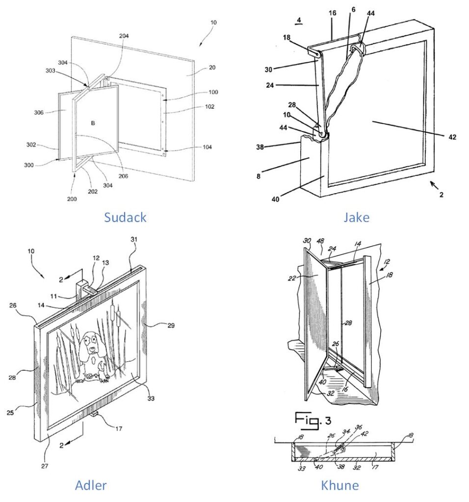
Reversible Frame Patent Examples
When my retirement day finally arrived, I culled my list, did a few small projects and then started on what would eventually become the flippee.
I wanted to create something useful and original. Something that I could protect with a patent and sell. To do so, I’d need to check out what was already out there. When I did, I was not impressed. Many desktop flip frames were available, but no wall-mounted version existed. I also checked the existing patents (see picture), but none were commercially available.
All the existing designs hid the flipping mechanism or were difficult to use.
Worse, each of the original designs lacked something fundamental to using a double-sided frame – Double-sided content.
I soon realized that there already was a source for double-sided content – sports trading cards! I also realized that the my design, with two pivot arms on the top and bottom, was not already patented!
I read several books on patents and started work on submitting for a patent.
Document, document, document
One of the first things that they tell you when you’re developing Intellectual Property (IP) is to always document what you’re doing – good, bad, or ugly. Much of my work was documented in an old engineering notebook (see photo), but most of the work was saved in a word file that I used to document EVERTHING. As a result, this file is now about 400 pages, and includes drawings, calculations, notes, design concepts, etc.
It’s also important to date your entries as these dates are your evidence of when you developed the ‘inventive concepts’ of your product. They might be helpful in a patent dispute with someone that has a similar concept.
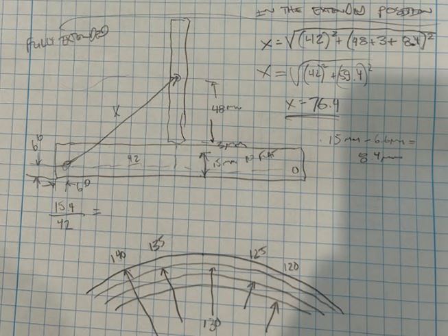
of a curved pivot arm
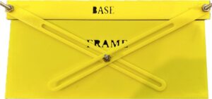
Early Prototype
Early Frame – Nice to look at –
Impossible to build
I bought a 3D printer and started designing some prototypes. My first prototypes focused on basic pivot arm tests (see picture). I started building early prototypes with acrylic windows and found that they were difficult to work with, cracked, and were expensive to manufacture.
My first fully operational frame had an acrylic window, and about 30 parts (see photo). It was an engineering marvel, and completely unsuited to any type of production.
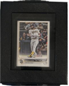
When I later bought a magnetic holder to protect a rare card I own, I realized that it solved many of my design problems. First it was very hard, very clear, easy to load, and provided UV and water resistant protection! I redesigned the frame to be smaller and to hold the magnetic holder instead of using external glass. The smaller frame was easier to turn and much more protective.
My son recommended curved pivot arms and I builit my first ‘production’ flippee. It featured rubber band retraction, and many of the features of the modern flippee. It was also prone to fail if any of its 3D parts were printed wrong – which was a recurring theme.
So much of my work was related to design improvements that I bought another 3D printer and kept both of my printers working almost non-stop.
flippin’ nice
The great thing about a rubber band retraction method is that it is cheap. Unfortunately, that’s the only good thing about this method! I committed to working with springs, even if it required a completely new redesign – and it did.
With my ego now in check, I went back to the drawing board and redesigned the frame with spings on each corner. About 8 months later, the production #2 design was ready. Production #2 was a working, well-made frame that flipped easily and was easy to flip (see video).
I built a small robot that I called, ‘the Terminator’, to test the flipping. This was a great source of entertainment and I recorded every flip with my camera phone. Often the Terminator would do its job, flipping the frame about 1500 flips an hour with no fanfare. Other times, a failure would show itself with spectacular results! (see video)
I built 100 of these first production frames, each with a card installed within. Still, as i assembled each 3D printed frame, I realized that the consistency of the construction was not great. For a print time of 1 day per flippee, it was just not economically feasible to build these ‘production’ frames.
Terminator Destroys